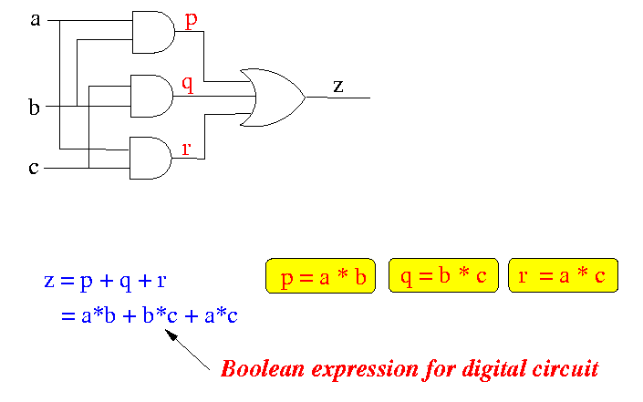
- A (combinatorial) digital circuit always implements some
boolean expression.
This boolean expression can be obtain by tracing the
paths through the digital circuit:
Example:
- A boolean function can be realised by one or more digital circuits.
- The problem that we are interested is how to design a digital circuit that implement some function that we desire.
- This problem is called circuit design problem.
- Before we tackle this problem, let's give some more background on the problem....
- As mentioned above, there are many different digital circuits
that will implement the same boolean function.
- Some circuit that implements the boolean function uses more transistors
or gates, other circuits use less gates, nevertheless,
they implement the same boolean function.
- The circuit that uses the least number of gates to realise
the boolean function is called the optimal circuit.
- Finding the optimal circuit is called
circuit optimazation
- The circuit optimization problem is NP-complete,
in layman's terms: it is very hard to construct a computer
algorithm (program) that solves the circuit optimization problem.
- This course is not about circuit optimization, but to understand the functionality of a computer.
- Although the finding the BEST circuit that realises
a given boolean function is NP-complete (difficult), finding
some circuit is very easy.
- In fact, there is a simple algorithm that you can use to
design a digital circuit for any boolean function.
- I will illustrate the circuit design algorithm with an example next.
- Design a digital ciruit with 3 inputs and 1 output
- The value of the output is 1 if two or more of the input values are 1
- The value of the output is 0 otherwise (note: this is implied, since the output value can only be 0 or 1).
- Set up the logic table for the boolean function
- i.e., List the function values for every possible input values
- In this example, the table for the boolean function described above
is:
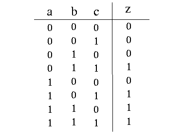
- In this example, the table for the boolean function described above
is:
- Use and gates to connect to the combinations
of input signals that generate 1 in the output.
- In the example above, the input combinations that generate
output = 1 are:
- a = 0, b = 1, c = 1
- a = 1, b = 0, c = 1
- a = 1, b = 1, c = 0
- a = 1, b = 1, c = 1
- For each combination, use 1 and gate to connect
the combination:
- This can be achieved using a multi-input and gate, as
follows....
- if a signal is 1 in the combination, connect the signal itself
to the input of the and gate
- if a signal is 0 in the combination, connect the inverse signal to the input of the and gate
- This can be achieved using a multi-input and gate, as
follows....
- The following is the connection generate by step 2 of the algorithm:
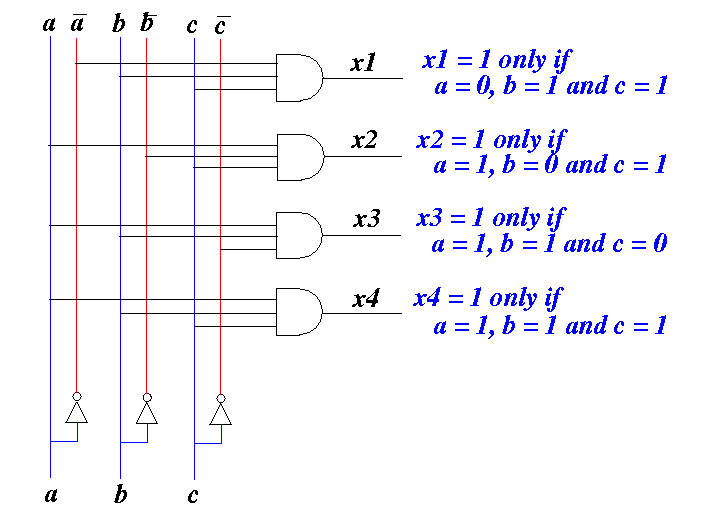
- Note: we used and-gates with 3 inputs. For a description of the behavior of and-gates with 3 or more inputs, see the following class note: click here
- In the example above, the input combinations that generate
output = 1 are:
- Connect the outputs of all the and-gates in step 2 with
a multi-input or-gate
- Resulting circuit:

- The output z of this circuit is 1 if and only if one of the
variables x1, x2, x3 or x4 is 1.
- One of x1, x2, x3 and x4 is 1 if and only if
the inputs are: { {a=0, b=1, c=1}, {a=1, b=0, c=1}, {a=1, b=1, c=0},
{a=1, b=1, c=1} }
- Therefore, output z of this circuit is 1 if and only if the inputs are: { {a=0, b=1, c=1}, {a=1, b=0, c=1}, {a=1, b=1, c=0}, {a=1, b=1, c=1} }
- The output z of this circuit is 1 if and only if one of the
variables x1, x2, x3 or x4 is 1.
- Conclusion: the circuit does exactly what we want...
- See how the circuit works: click here