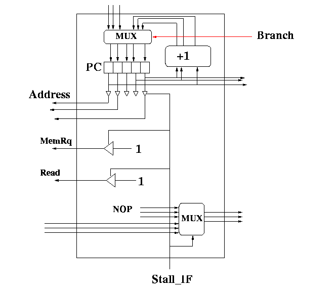
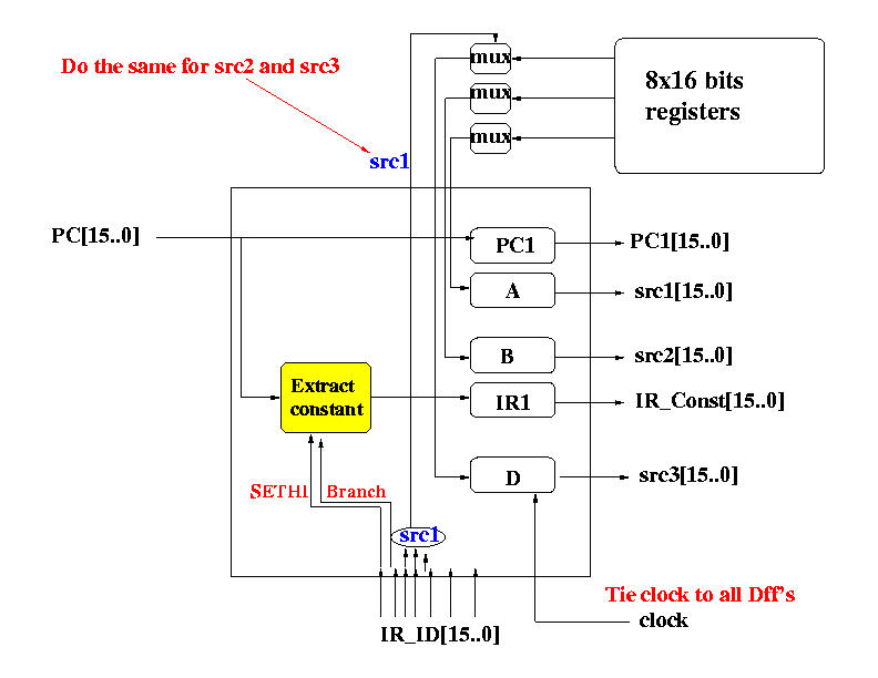
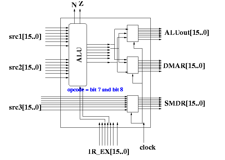
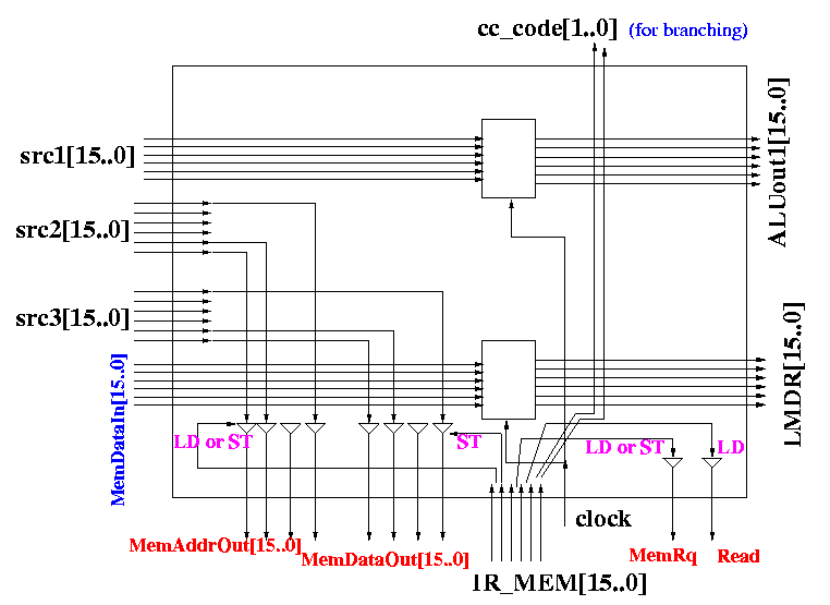
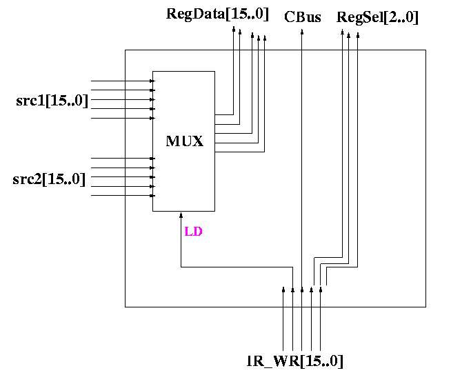
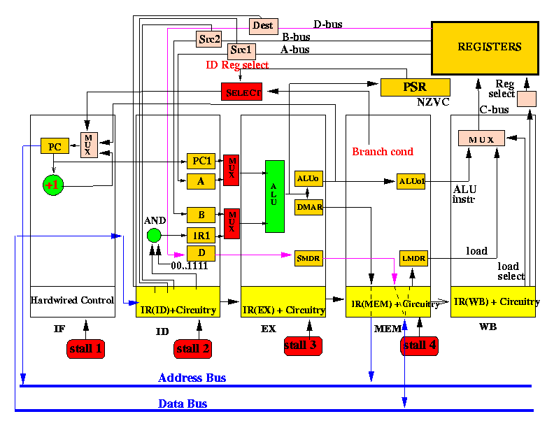
- In this project you will make 2 pipelined CPUs:
- The basic pipelined CPU
- The advanced pipelined CPU
- I will design the CPUs modules in such a way that you can
reuse the basic piplelined CPU in the advanced pipelined CPU.
- All you need to do is to add extra multiplexors (with pretty complicated control logic) and other logic circuits between the stages to get the advanced pipelined CPU.
- The Basic Pipelined CPU:
		                 constant
		                     flag
		      Dest              |     Scr1        Src2
		  |<--------->|         V |<--------->|<--------->|
  +---+---+---+---+---+---+---+---+---+---+---+---+---+---+---+---+
  | A | B | C | D | x | x | x | c | c | f | x | x | x | x | x | x |
  +---+---+---+---+---+---+---+---+---+---+---+---+---+---+---+---+
    15  14  13  12  11  10  9   8   7   6   5   4   3   2   1   0
  |<------------->            |<----->|
     opcode                       ^
		                  |

                                 cc = ALU opcode
			                  00 = add
			                  01 = subtract
			                  10 = and
			                  11 = not
		                    or branch condition
			                  00 = no branch
			                  01 = branch if N = 1
			                  10 = branch if Z = 1
			                  11 = always branch

   ABCD encodes the operation/instruction as follows:


   A = 1 ---> LD instruction
   B = 1 ---> ST instruction
   C = 1 ---> Branch instruction (cc encode the branch condition)
   D = 1 ---> SETHI instruction

   ABC = 0000 ---> ALU instruction (cc encodes the operation)

   Other combinations are not used (so decoding instruction is very easy)
|
- There are 3 kinds of instructions that uses constants embedded
inside the instruction:
- ALU instruction
- Sethi instruction
- Branch instruction
Each type of instructions encode their constant differently and we must extract it differently, depending on the instruction type (you guess it, use MUXes...)
- The constant used by ALU instructions is contained by
the Src2 field:
		                 constant
		                     flag
		      Dest              |     Scr1        Src2
		  |<--------->|         V |<--------->|<--------->|
  +---+---+---+---+---+---+---+---+---+---+---+---+---+---+---+---+
  |   |   |   |   |   |   |   |   |   | 1 |   |   |   | x | x | x |
  +---+---+---+---+---+---+---+---+---+---+---+---+---+---+---+---+
							 Constant
- The SETHI constant is encoded as follows:
		      Dest
		  |<--------->|
  +---+---+---+---+---+---+---+---+---+---+---+---+---+---+---+---+
  |   |   |   | 1 |   |   |   | x | x | x | x | x | x | x | x | x |
  +---+---+---+---+---+---+---+---+---+---+---+---+---+---+---+---+
						 Constant
The SETHI instruction shifts the constant over by 3 bits and store the result in the Dest register.
So you should output this value when it is a SETHI instruction:
  Forming the SETHI constant:


    15  14  13  12  11  10  9   8   7   6   5   4   3   2   1   0
  +---+---+---+---+---+---+---+---+---+---+---+---+---+---+---+---+
  |   |   |   | 1 |   |   |   | a | b | c | d | e | f | g | h | i |
  +---+---+---+---+---+---+---+---+---+---+---+---+---+---+---+---+
                                                 Constant


  Constant used in operation:

  +---+---+---+---+---+---+---+---+---+---+---+---+---+---+---+---+
  | a | a | a | a | a | b | c | d | e | f | g | h | i | 0 | 0 | 0 |
  +---+---+---+---+---+---+---+---+---+---+---+---+---+---+---+---+
Don't use shifters to accomplish this. This can be done easily by "creative connection". Connect the input "shifted over" to a different multiplexer input - just like in a multiply circuit.
- The Branch instruction also uses a constant offset and it is encoded
as follows:
    15  14  13  12  11  10  9   8   7   6   5   4   3   2   1   0
  +---+---+---+---+---+---+---+---+---+---+---+---+---+---+---+---+
  |   |   | 1 |   | x | x | x | x | x | x | x | x | x | x | x | x |
  +---+---+---+---+---+---+---+---+---+---+---+---+---+---+---+---+
				 Constant offset
You must sign-extend the constant offset also.
- How to extract the differet constants - here's a circuit
that illustrates how to extract the various constant
depending of the instruction (use Muxes ofcourse...):

You need this "constant extraction circuit" inside the ID stage
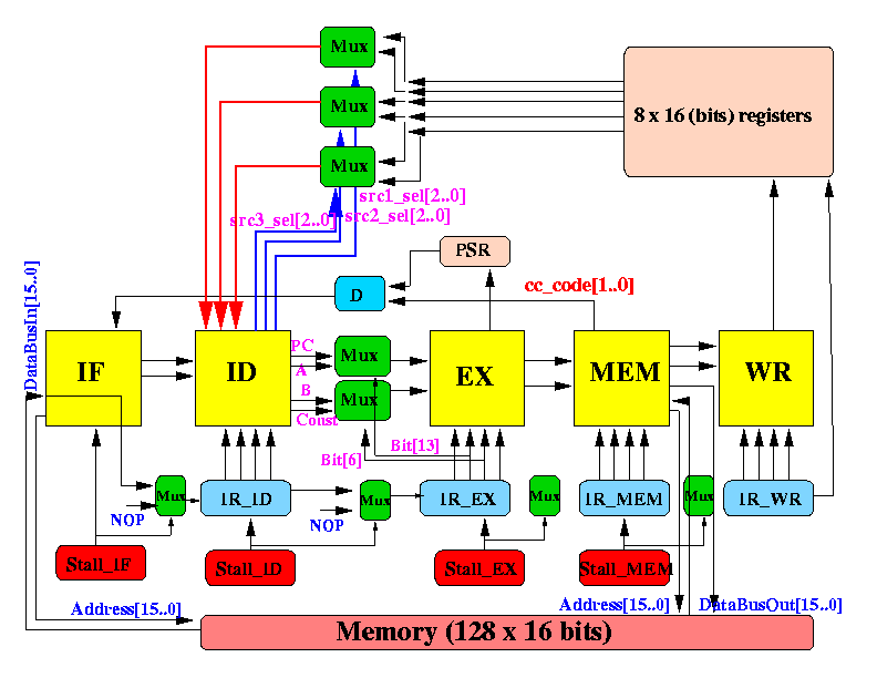
- The different components (macros) and their connections
are given in this figure:
-
The meaning of the "red dots" in the above figure:
- The "red dots" represent the common way to handle stalling
in the pipeline.
- When a stage stalls, it does the following:
- Do not generate a clock signal (that write the IR
of that stage)
- Send a NOP instruction as output
- Do not generate a clock signal (that write the IR
of that stage)
- The "red dots" represent the common way to handle stalling
in the pipeline.
- Example 1:
If Stall_IF = 1 then:
- Do not generate a clock signal that write the IR
of the IF stage (since IF does not have an IR register,
this step is void)
- Send a NOP instruction as output to the IR_ID register
- Do not generate a clock signal that write the IR
of the IF stage (since IF does not have an IR register,
this step is void)
- Example 2:
If Stall_ID = 1 then:
- Do not generate a clock signal that write the IR
of the ID stage (so the instruction in IR_ID does not change)
- Send a NOP instruction as output to the IR_EX register
- Do not generate a clock signal that write the IR
of the ID stage (so the instruction in IR_ID does not change)
NOTE:
This is extremely important...
By default, all Dff (registers) are
written
at the
END of the clock:
       		+--------+
		|	 |
		|	 |
		|	 |
       +--------+	 +

			 ^
			 |
			 |
			 |
		   Update Dff (registers)
|
There are some registers that must be updated in the MIDDLE of the clock:
       		+--------+
		|	 |
		|	 |
		|	 |
       +--------+	 +

	        ^
	        |
	        |
	        |
	  Update Dff (registers)
|
I will indicate that explicitly in the design notes.
- IF
- ID
- EX
- MEM
- WR
- Decision circuit D
(magenta colored component in diagram)
- Stall logic circuit Stall_IF
- Stall logic circuit Stall_ID
- Stall logic circuit Stall_EX
- Stall logic circuit Stall_MEM