CS355 Sylabus
Executing an ALU instruction: Part 1 - Register with Register
We now examine in detail how the basic pipeline CPU execute
the 3 different types of instructions.
- ALU instructions with 2 register source operands
- Step 1: Fetch
- At start of the CPU cycle, the IF stage sends out PC
- At end of the CPU cycle, the IR(ID) register is updated with
the instruction fetched (ADD R1, R2, R3)
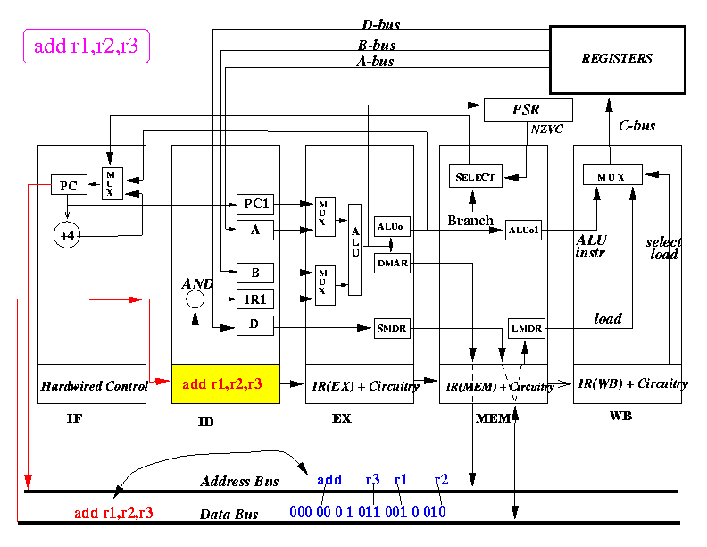
- The picture above depicts the content of the CPU at end of the first
CPU cycle (and the start of the 2nd cycle)
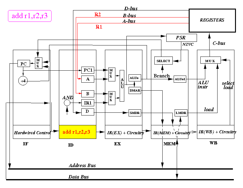
- Step 2: Decode (fetch operands)
- At start of the CPU cycle,
the ID stage sends out selection
signal that
selects values from R1 (on A bus) and R2 (on B bus)
:
- At end of the CPU cycle, A register is updated with R1,
B register is updated with R2 and
D register is updated with R3.
(But only registers A and B will actually be used, register D
will not be used in this instruction).
- Also, at the end of the CPU cycle, the instruction (ADD R1, R2, R3) is
moved into IR(EX) and a new instruction is fetched into IR(ID)
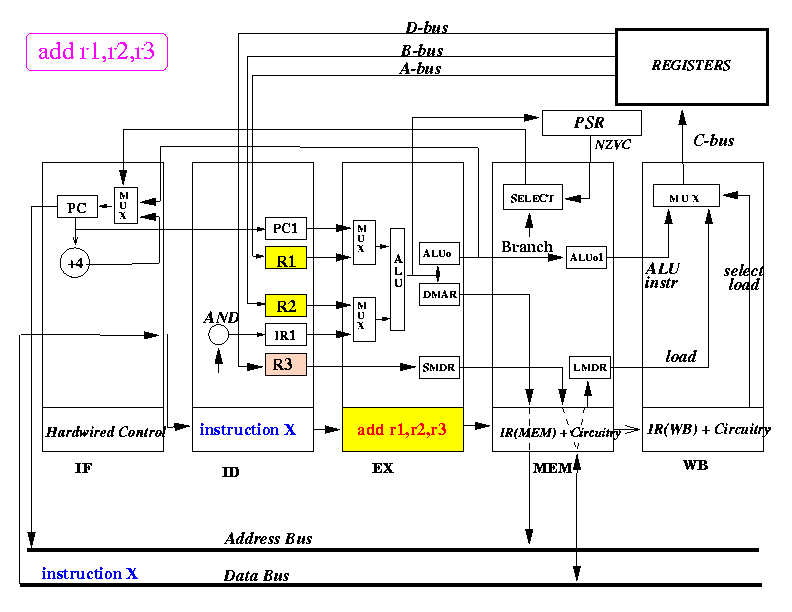
- The picture above depicts the content of the CPU at end of the second
CPU cycle (and the start of the 3rd cycle)
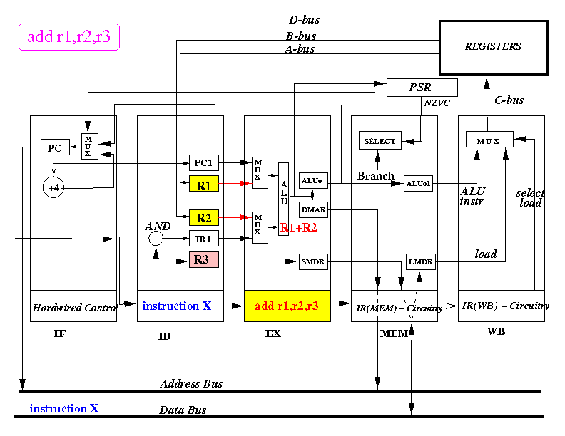
- Step 3: Execute (compute)
- At start of the CPU cycle,
the EX stage selects
values from R1 and R2 for the ALU, use the ALU opcode
to make ALU add the input values
- At end of the CPU cycle, ALUo and DMAR registers is updated with
the value R1+R2 and SMDR register will be updated with the value R3
(R3 will not be used - see next step).
- Also, at the end of the CPU cycle, the instruction (ADD R1, R2, R3) is
moved into IR(MEM) and a new instruction is fetched into IR(EX)
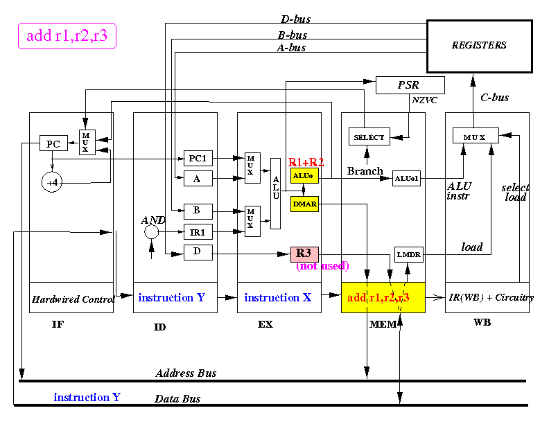
- The picture above depicts the content of the CPU at end of the 3rd
CPU cycle (and the start of the 4th cycle)
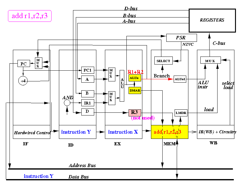
- Step 4: Memory Access or Branch
- Because the MEM stage of the basic pipelined CPU is used
to execute memory access and branch instructions,
and "ADD R1, R2, R3" is neither, there is no processing
taken place in the MEM stage.
- At end of the CPU cycle, ALUo1 registers is updated with
the value R1+R2
- At the end of the CPU cycle, the value R3 in SMDR register
is discarded (SMDR register is
only used in a STORE instruction - see later)
- Also, at the end of the CPU cycle, the instruction (ADD R1, R2, R3) is
moved into IR(WB) and a new instruction is fetched into IR(MEM)

- The picture above depicts the content of the CPU at end of the 4rd
CPU cycle (and the start of the 5th cycle)
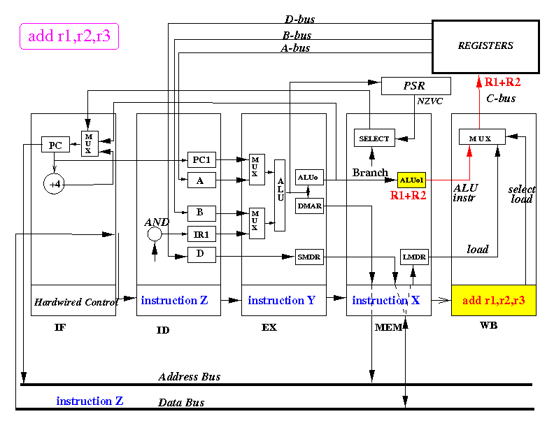
- Step 5: Update register
- At the start of the CPU cycle, the destination register (R3)
is selected by the Dest field of the IR(WB)
and the value in ALUo1 (= R1 + R2) is selected for output
on the C-bus (because the instruction is an ADD)
- At end of the CPU cycle, the register R3 register is updated with
the value R1+R2
- Also, at the end of the CPU cycle, the instruction (ADD R1, R2, R3) is
discarded and a new instruction is fetched into IR(WB)
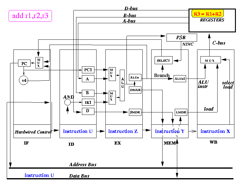
- The picture above depicts the content of the CPU at end of the 5rd
CPU cycle (and the start of the 6th cycle)