Identifying (= addressing) the special purpose registers in an IO device
 

  • In order for the CPU to read/write the special purpose registers in an IO device, these registers (= memory cells) must be addressable on the system bus

    I.e.:

      • Each special purpose registers in an IO device is assigned a unique address on the system bus !!!

  • There are 2 techniques used to assign addresses to the registers in an IO device:

      1. Standard IO:   uses a separate IO address space

      2. Memory-mapped IO:   uses a subset of memory addresses to identify (= address) registers in IO devices

The Standard IO addressing technique
 

  • In the standard IO technique, IO devices and memory location use separate address spaces

  • Two separate "address spaces" are implemented using two (=2) different signals that identify the 2 address space

  • Analogy: suppose 2 lotto games both have 6 numbers

      • The winning numbers in Lotto game 1 can be 1 2 3 4 5 6
      • The (same) winning numbers in Lotto game 2 can be also be 1 2 3 4 5 6

    The winning numbers (1 2 3 4 5 6) in lotto game 1 are technically different than the winning numbers (1 2 3 4 5 6) in lotto game 2 - although they are the same numbers !!!

    (E.g.: they will win a different amount of money...)

How to implement separate memory address and IO address spaces
 

The MReq signal signals a memory address and the IOReq signal signals an IO device address.

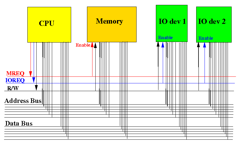
The CPU will only assert one of the MReq or IOReq signals !!!

CPUs that uses the standard IO addressing technique

  • A CPU/system bus that uses the standard IO address technique must have the MReq signal and the IOReq signal

    Example: the Intel 8085


    When the signal IO/M=0, the 8085 CPU signals a memory address
    When the signal IO/M=1, the 8085 CPU signals an IO device address

CPUs that uses the standard IO addressing technique

  • A CPU/system bus that uses the standard IO address technique has separate assembler instructions for memory access and IO access:

    Example: the Intel 8085

         mov   instruction access the memory
         in    instruction inputs data from an output device 
         out   instruction outputs data to  an output device
      

    When the 8085 CPU executes a mov instruction, it sends out IO/M=0
    When the 8085 CPU executes an in or an out instruction, it sends out IO/M=1

The memory-mapped IO addressing technique

  • In the memory-mapped IO address technique, the IO devices and the main memory share the same address space

    I.e.: the CPU/system bus that uses memory-mapped IO only has the MReq signal !!!


The memory-mapped IO addressing technique

In memory-mapped IO, the address space is partitioned into 2 disjoint ranges

Example of a address space partitioning:

         Address (binary)                        Use for
    -----------------------------------------------------------
        00000000 00000000 00000000 00000000      Memory
        00000000 00000000 00000000 00000001      Memory
        00000000 00000000 00000000 00000011      Memory
	....
        11100000 00000000 00000000 00000000      Memory
        11100000 00000000 00000000 00000000      Memory
	....
        11101111 11111111 11111111 11111111      Memory
	11110000 00000000 00000000 00000000      IO device
	11110000 00000000 00000000 00000001      IO device
	....
	11111111 11111111 11111111 11111111      IO device
  

Combinatorial circuits are used to translate the ranges to activate memory/IO devices

The memory-mapped IO addressing technique

Circuits to implement the address space partitioning in the previous example:


The memory-mapped IO addressing technique

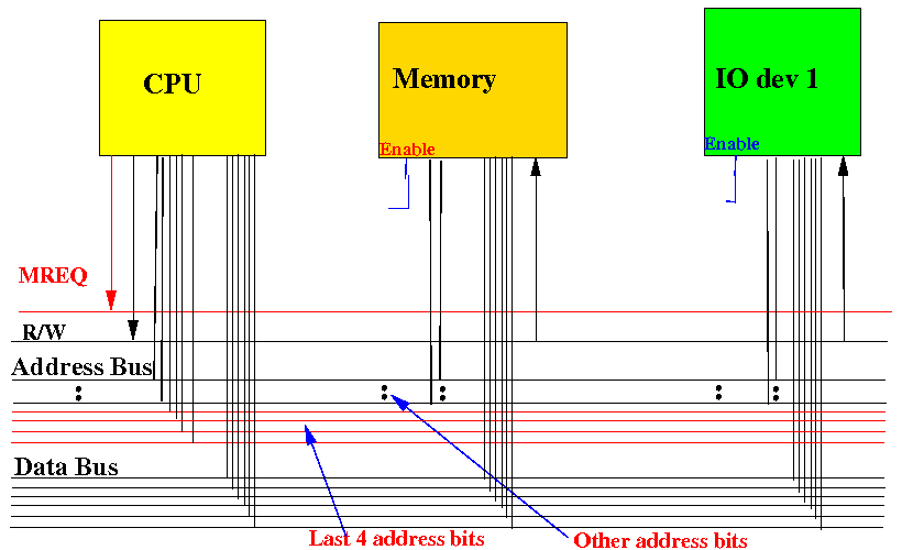
We enable an IO device when MReq=1 and when the last 4 bits in the address=1111:


The memory-mapped IO addressing technique

We enable an IO device when MReq=1 and when the last 4 bits in the address≠1111:


CPUs that uses the memory-mapped IO addressing technique

  • A CPU/system bus that uses the memory-mapped IO address technique do not have both the MReq signal and the IOReq signal

    Example: the Motorola 68000


    The Bus Control signals do not contains an separate IOReq indication.

CPUs that uses the Memory-Mapped IO addressing technique

  • A CPU/system bus that uses the Memory-Mapped IO address technique has one assembler instructions for both memory access and IO access:

    Example: the Motorola 68000

         move   instruction access the memory    
                and IO devices
      
        (ARM: uses ldr to access memory and IO devices)  
      

  • In the previous example:

      • When the move instruction specifies an address that is 1111xxxxxxxx...xxxxxxxxxx, the circuitry will enable an IO device

      • Otherwise, the circuitry will enable the memory !!!