If you would ask a fellow human to compute 3 + 4, he/she would most likely only do "3 + 4", he/she would not compute "3 - 4", "3 * 4", "3 / 4", etc, etc. because you did not ask for it.
The ability of the ALU to do the different kinds of operations is derived from a many-to-one switch... yep, the multiplexor:
- The ALU performs every possible operation on its inputs and then use multiplexors to pick out the desired result.
Our ALU will only have 4 operations: +, NOT, AND and OR....
And the operands (and result) of the ALU are 4 bits long...
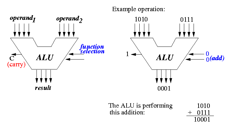
To select the desired operation among the 4 different possible operations, we will need 2 "function" bits:
- 00 will mean: operand1 + operand2
- 01 will mean NOT(operand1)
- 10 will mean operand1 AND operand2
- 11 will mean operand1 OR operand2
The following figure shows our ALU and an example operation:
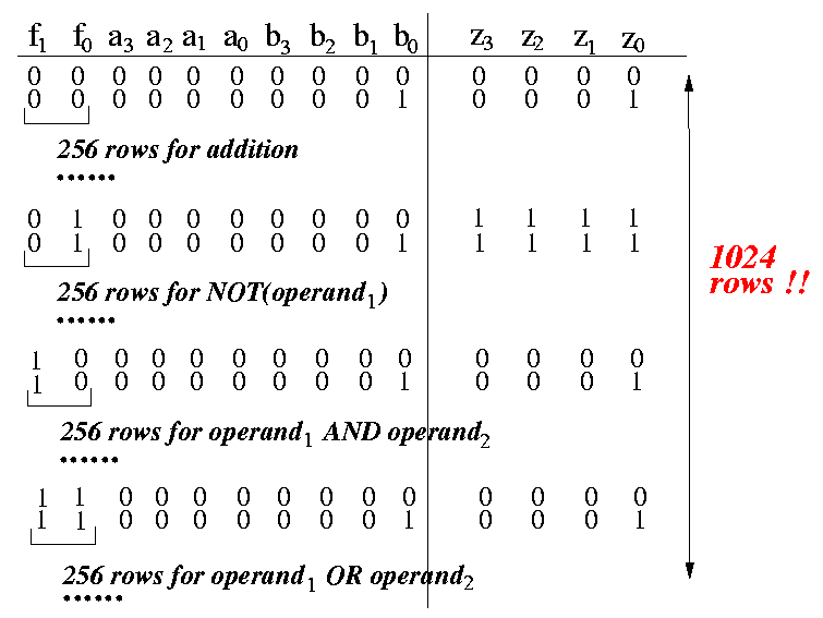
To give you an idea what kind of trouble we are dealing with, the following figure shows a glimpse of the logical table that you would obtain when you apply the circuit design technique given in the class notes ( click here):
We will first design a 1-bit-ALU circuit that can perform the desired operations on 1 bit operands.
We will than cascade this 1-bit-ALU circuit to obtain an ALU that can perform the desired operations operands of any length.

- The inputs of the circuit are:
- a = operand1
- b = operand2
- cin = carry in (we need that to do addition)
- The outputs of the circuit are:
- result = outcome of the operation
- cout = carry out (we need that to do addition)
- The circuit first computes all the possible outcomes: a+b, NOT(a),
(a AND b), and (a OR b).
- The desired result is then selected using a multiplexor,
the control signal of the multiplexor will be the
operation code in the computer instruction
(stored in the IR - instruction register)
- I have a logic-sim circuit program that illustrates the operation of this 1-bit ALU: click here .

- Note: I did not complete the connections from
a1, a2, b1 and b2
to the inputs of their 1-bit ALU's.
From the figure, from the material on the 4-bit adder
( click here),
and from class notes, it should be clear how they should be
connected.
- Same note on the connection from the 1-bit ALU to the outputs z1 and z2.